ODIN 3D & 4D DETAILS STEPPERMOTOR-BOARD


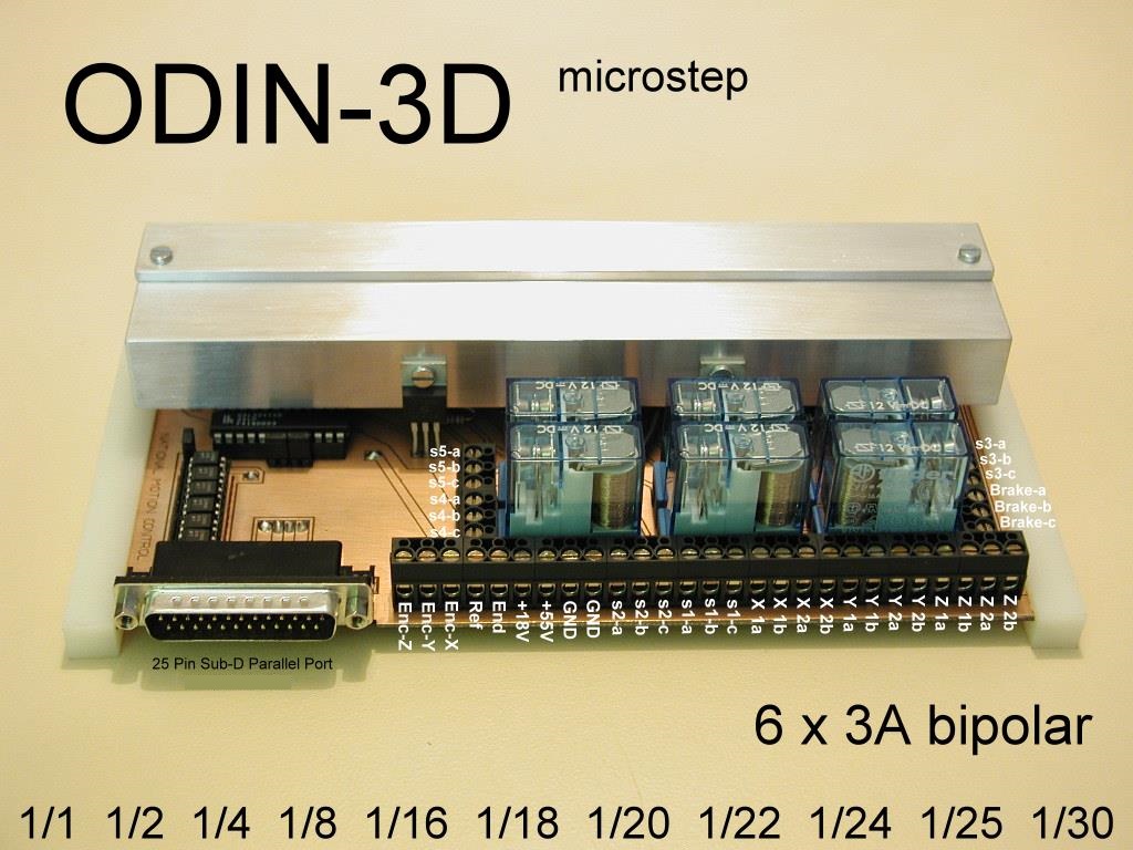
Odin-3D

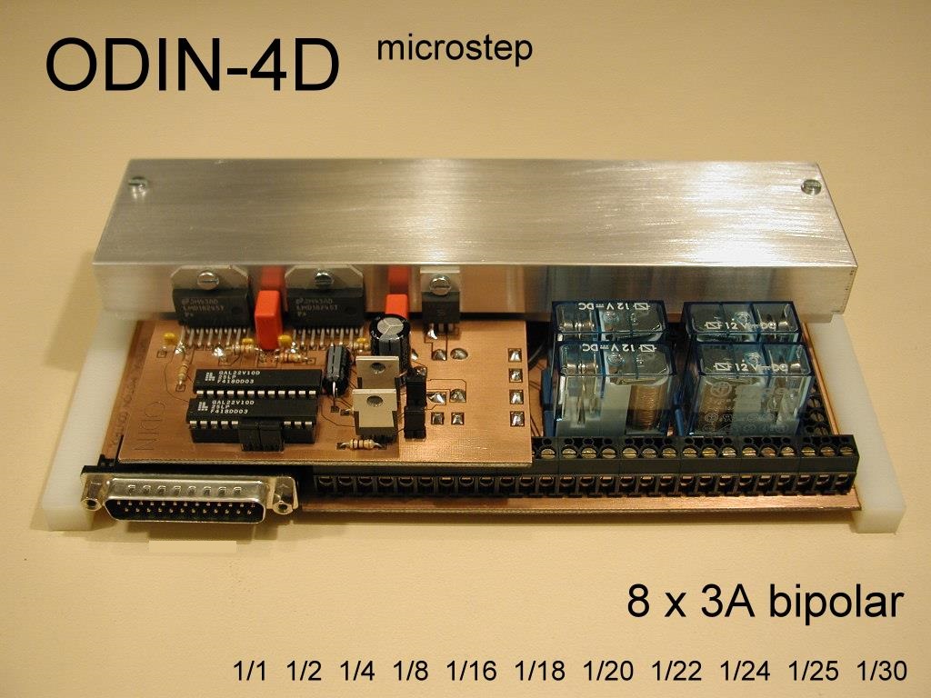
Odin-4D
Information about wiring the Odin-3D with 1D-Additional Board, look here: ODIN-4D


Wiring:
Enc-Z: Encoder-Z Signal Input 5V TTL, wired directly to Pin15 from Sub-D Port.
Enc-Y: Encoder-Y Signal Input 5V TTL, wired directly to Pin13 from Sub-D Port.
Enc-X: Encoder-X Signal Input 5V TTL, wired directly to Pin12 from Sub-D Port.
Ref: Reference Switch 5V TTL, X,Y,Z-Serial wired directly to Pin11 from Sub-D Port.
End: End Switch 5V TTL, X,Y,Z-Serial wired directly to Pin10 from Sub-D Port.
+18V: Input Voltage for Logic and Relays, 2A [min/max =12V/18V].
+55V: Input Voltage for Power, 14A [min/max =24V/55V].
GND: Input Ground for Logic and Relays.
GND: Input Ground for Power.
s2-a,b,c: Output Relay s2.
s1-a,b,c: Output Relay s1.
X 1a: Output Power X-Axis Phase 1a.
X 1b: Output Power X-Axis Phase 1b.
X 2a: Output Power X-Axis Phase 2a.
X 2b: Output Power X-Axis Phase 2b.
Y 1a: Output Power Y-Axis Phase 1a.
Y 1b: Output Power Y-Axis Phase 1b.
Y 2a: Output Power Y-Axis Phase 2a.
Y 2b: Output Power Y-Axis Phase 2b.
Z 1a: Output Power Z-Axis Phase 1a.
Z 1b: Output Power Z-Axis Phase 1b.
Z 2a: Output Power Z-Axis Phase 2a.
Z 2b: Output Power Z-Axis Phase 2b.
s5-a,b,c: Output Relay s5.
s4-a,b,c: Output Relay s4.
s3-a,b,c: Output Relay s3.
Brake-a,b,c: Output Relay Brake.


From Parallel Port optical coupled Relays with max. 16A/=24V resistence load.
The Optocoupler [PC 815] can be used for switching external Power-Relays.
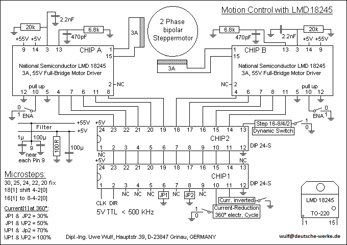
All Phase-Currents are adjustable with interchangable Resistors in the Range 0.1 - 3.0A.
Up to 1A Phase-Current no Fan is needed. Over 1A cooling with a Fan Dia 80mm [4m/s].
Clock Pulsing and Data Safety testet with min. 500000 Microsteps/sec.!
The autom. Current-Reduction and the Relay Brake are activated through Pin1(high).
Inverting the Current-Reduction (active = low): Pin11 at GAL Chip1 connect to GND.
Current-Reduction at Jp1 & Jp2 adjustable in Steps at 100% (inactiv), 75, 50 or 30%.
The dynamic Stepshift is realised through the Relay-Function s5 and Jp3 Connector.
All Functions are supported by our 9 Axis 6D CNC Milling-Programm.
Here you get to the FAQ of our CNC Program.


CONNECTING THE 25-PIN SUB-D PRINTERPORTS 378h 278h 3BCh:
with the 9 AXIS 6D CNC MILLINGPROGRAM (from Wulf)
Standard! No special wiring at Sub-D Port required!

Clock & Boost X,R,U (Pin2) Direction X,R,U (Pin3) GND X,R,U (Pin19)
Clock & Boost Y,S,V (Pin4) Direction Y,S,V (Pin5) GND Y,S,V (Pin20)
Clock & Boost Z,T,W (Pin6) Direction Z,T,W (Pin7) GND Z,T,W (Pin21)
Spindlemotor-Relay s1 (Pin8) GNDs1 (Pin22)
Coolingpump-Relay (pulsed) s2 (Pin9), inverted GNDs2 (Pin22)
1.Additional-Relay (Fullversion) s3 (Pin14), inverted GNDs3 (Pin25)
2.Additional-Relay (Fullversion) s4 (Pin16) GNDs4 (Pin25)
3.Additional-Relay (Fullversion) s5 (Pin17), inverted GNDs5 (Pin25)
Current Reduction & Hardware Brake (Pin1), Fullvers. inverted GND (Pin18)
Reference-Switch (Pin11) Start, when Pin11 Low GND (Pin23)
End-Switch (Pin10) Stop, when Pin10 High GND (Pin24)
Step-Encoder (Pin12/13/15) Auto-Correction of Realpos. GND (Pin24/24/23)


CONNECTING THE 25-PIN SUB-D PARALLELPORTS
with friendly support from DIRK HAUPT as Word-Document
for following CNC-Programms:


PCNC (Burkhard Lewetz)
CNC CAM/CNC Profi V3.1 (Preg Datentechnik)
CNC Profi up V3.21 (Preg Datentechnik)
BiSTEP 1A (QUAX) (Möller & Huth)
BiSTEP 2A (Farol CNC) (Möller & Huth)


PHASECURRENT LMD18245T-MOTOR-DRIVER
through RESISTOR R_steck at Pin13 and R_Phase(min) = 0.3 Ohm:

I_Phase [A] R_steck [Ohm]
3.0 6800
2.5 8200
2.0 10000
1.6 13000
1.0 20000
0.5 39000


Odin-3D Kit

Click here to choose the Controller Chipsets.

The Additional Board for 4. Axis is available now!


National-Motion-Control   Dipl.-Ing. Uwe Wulf   Hauptstr. 39   D-23847 Grinau    AGB